Operating Manual for S/V "Iwalani"
Specifications:
Documented # 1090898
42 ft length on deck
50 ft overall
37 ft waterline
12.5 ft beam
7 ft draft
55 ft waterline to top of mast
Displacement 44,000 lbs
Systems
Overview:
Steering: Tiller w/ trim tab. You MUST attach
autopilot ram to center trim tab, even if you are NOT using the autopilot.
Otherwise, rudder will be out of trim and the boat will be IMPOSSIBLE to hand
steer.
Sail: gaff rigged main, club footed staysail, jib
with 2:1 sheet blocks, 100% light air jib. Engine: Diesel 63 hp
Westerbeke 1,750rpm gives 5.5 knots calm conditions.
Fuel: 3-50 gal tanks. Range 1,000nm @ 1,000 rpm (calm
conditions).
Water: 1-30 gal plastic, 1 Nauta 50 gal flexible
tank, 1-10gal hot water tank. =90gal total
Electric: 4-8D Lifeline AGM batteries 1,100 amp hours
total. 2 banks (2 batteries each).
Charging systems: 12 volt 160 amp engine alternator
with Lifeline regulator.
Windbaron Wind generator 12 volt ~20 amps @ 20 knots true
wind.
Inverter: 1800 watt Pro-Sine 12 volt to 110 volt 60
cycle.
Watermaker: Spectra 360 12 volt system. Up to 16 gph
@ 14 volts.
Communications:
Icom SSB with Ham frequencies.
Inmarsat-C with distress transmitter, GPS, EGCs, text high
seas weather and e-mail.
EPIRB 406 Satellite position, vessel ID reporting.
Bilge Pumps:
Rule 2000 automatic with float switch under the companionway
steps.
Switch (auto, off, manual) on port side nav station, aft of
main electric panel.
Rule 8000 just forward of engine.
Switches on lower left of the electric panel.
Whale Gusher 10 in cockpit.
Whale Gusher 30 under forward end of quarter berth, remove
nav station seat to access.
Fire:
Halon automatic fire system in engine room.
Hand held halon at nav station.
Salt water wash-down pump fitting at starboard chainplates.
Ground Tackle:
Maxwell double chain/double rope 12 volt windless.
65 lb CQR on 300 ft 3/8 inch chain (starboard side).
45 lb CQR on 150 3/8 chain and 150 ¾ inch nylon (port side).
100 lb Luke Storm Anchor (Yachtsman style) in forward chain
locker.
Fortress stern anchor on 250ft 3/4 inch nylon.
STEERING: Attach autopilot ram to trim tab pin and adjust
ram to center trim tab arm. You can manually adjust ram length by screwing the
ram-rod in or out by hand. (In case of auto pilot failure or lack of electric
power.) You can also adjust ram length with autopilot in standby mode by
pressing the +1 1 buttons. When under way, while hand steering, adjust ram
length to remove any adverse helm. Auto-pilot draws 1 amp.
ENGINE:
Check oil and coolant level and fuel filter before starting.
To start, turn ignition key and listen for engine alarm.
Push in button on left (pre-heat) and hold for 10 seconds. Push button on right
while still holding left button. When engine starts WAIT for oil pressure to
rise BEFORE releasing left button. Oil pressure should be 50lbs at startup and
40lbs when warm. Voltage 13.5-14.5 normal. Check that the engine exhaust is
discharging water.
Controls: Single lever shift/throttle.
Fast idle in neutral (for charging batteries, cooling icebox)
can be obtained by pushing shift lever to port and tightening the screw near
the bottom of the lever. Run at 1,000 rpm
Normal operation is at 1,750 rpms. This gives 5.5-6 knots in
calm conditions.
Higher rpms give poor fuel economy at modest gains in speed.
Max speed 7knts in calm!
FUEL MANAGEMENT:
Tanks located in engine room. Two starboard, one port. Deck
fills directly above tanks. Vents inboard port and starboard bulwark, just
forward of cowl vents (aft of cockpit).
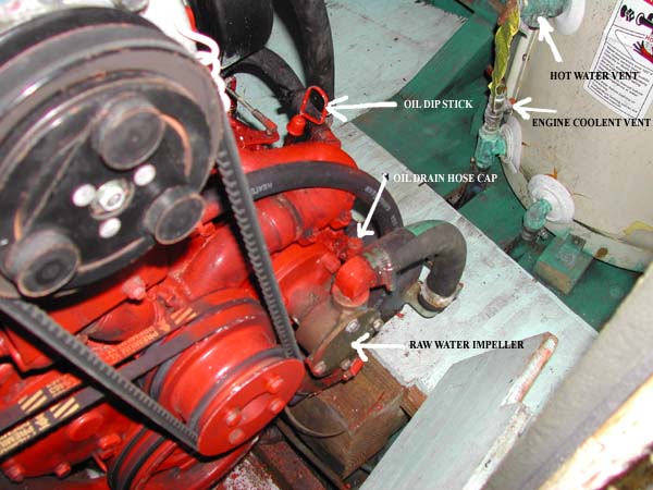
Dipstick fuel gauge.
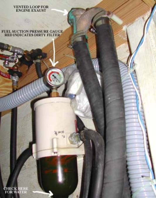
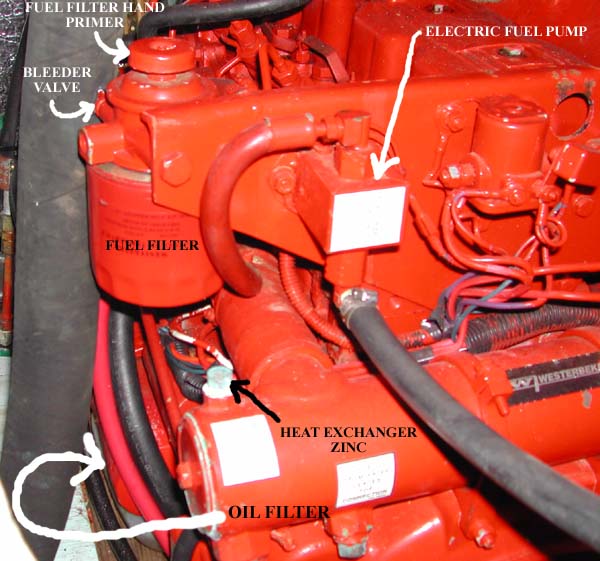
Racor filter located on starboard side of cockpit well
(above alternator).
Engine filter on aft port side of engine, just behind
cockpit drain hose.
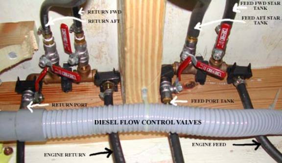
Fuel valves on overhead of engine room just aft of Racor.
Three feed valves forward of deck
beam and three return valves aft of deck beam.
Valve positions forward and aft of
beam SHOULD LOOK THE SAME. If not, you will be feeding from one tank and
returning to another!
Follow hoses on feed valves for
corresponding tanks.
Change oil every 100 hrs.
Run engine
to warm oil.
Place empty
oil container under forward end of engine (Just behind Rule 8000)
Remove cap from oil drain hose
(Forward port side of engine just behind raw water pump) with two end wrenches.
Place drain hose in empty container
and let drain for 30 minutes.
Remove oil filter with filter
wrench. (Kind that fits on the end of the filter is best.)
Using a small amount of oil to
lubricate rubber gasket, replace with new oil filter hand tight only! Do not
use a wrench.
Replace oil drain hose and cap in
holder.
Add oil. (About 1 US gallon)
Start engine and check for leaks at
filter.
CHECK EVERY MONTH:
Engine zinc located on the port side of engine heat
exchanger.(Small brass nut) Heat exchanger is the long round tube running
athwart-ships on back of engine.
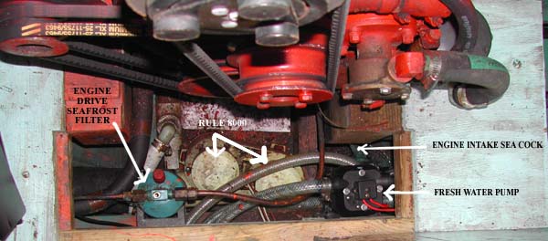
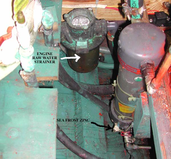
Sea Frost heat exchanger zinc (on bottom aft side of
exchanger with electric wire attached) Exchanger located on port forward engine
bed, partly under floorboards.
BATTERY MANAGEMENT
Normal voltage range.
Charging = 13.0v 14.6v
Not charging =
12.6v (no load) is 100% charged.
11.7 (small load) is 50% charged.
DO NOT let voltage drop below 11.7v
with a small load (cabin light)
There are switches for the windless, main panel, engine,
inverter and wind generator located on the forward side of the battery box.
CHARGING SYSTEMS
To charge bank 1 or 2 with the engine alternator, use the
middle battery switch (gray)
To charge banks with the wind generator, use the port most
switch (orange)
DO NOT HAVE THE WIND GENERATOR AND THE ENGINE CHARGING ON
THE SAME BANK. YOU WILL SET THE BOAT ON FIRE!! (The wind generator ballast
resisters see the charge from the engine as over-charge and get very hot!)
WIND GENERATOR:
The control panel is located on the port side of the nav
station.
There is and on/off switch (looks like a common house light
switch) and a second household type switch which is used to transfer excess
power between the ballast resisters and the hot water tank.
The small toggle switch labeled Display gives power to the
LCD display. When transmitting on the SSB, the generator should be turned off.
Stray EM from the antenna will blow out the display fuse. If the generator
cant be stopped with the main on/off switch, you have two choices. 1.) Leave
it running and turn off the display while transmitting. Or 2.) Use a boat hook
to grab the rope loop on the tail of the generator and turn the generator 90
degrees to the wind. This will stop the blades from rotating. If the blades
spin up after you let go with the boat hook you MUST RETURN THE SWITCH TO THE
ON POSITION, within fifteen seconds, otherwise you will damage the generator.
Wind generator blades should be tied off when the generator
is not being used. DO NOT TIE THE BLADES TO THE WIND GENERATOR MAST. You will
bend the blades (wood) and the tie will slide down the mast and fall off the
blade. Tie to the generator itself.
At very slow wind speeds, there is a tendency for the
generator mast to wobble. This is normal, but should be avoided if possible. At
present, the tilting safety mechanism is disabled. There is some wear in the
pivot and the generator vibrates. We encountered 60 knot winds without ill
effect, BUT it would not be safe if the winds were any higher.
The switch to transfer excess power
to the hot water tank is rarely used.
The most useful display to watch is
the volts/cell reading. Fully charged is 2.20
Both the toggle selector switch and
display output dial must have the same settings to work correctly.
The regulator control MUST remain
on 2.35 volts/cell to avoid battery damage.
The ballast resisters (the two
brown coil looking things just aft of the panel) get hot as the batteries come
up to full charge. I left them in the open so any fire hazard would be readily
apparent.
BATTERY MONITORS:
Use the Link 20 battery monitor (port side nav station) to
make sure charging correctly. Check bank 1 or 2 for voltage and amps. Amp hour
numbers are not reliable!
Analog battery gauge is on electrical panel.
Inverter control switch also shows battery voltage.
BATTERY FUSES:
There are, large, inline fuses between the alternator,
inverter and the batteries.
The small inline fuses at the grounding buss (below the
engine battery switch) are for the Link 20 battery monitor.
SAILS:
The mainsail has three reefs and the staysail has one. The
mainsail should be raised with the gaff horizontal till the throat is tight.
Then the peak should be raised. One person can raise the mainsail, if the
topping lift is taken up first. Once the halyards are sweated up the topping
lift should be slackened. On a beam reach, with a true wind of 18 knots, the
full main, staysail and working jib can be carried. Sail trim and reefing
should be determined by the behavior of the tiller while on autopilot. If the
tiller is showing signs of weather helm (banging into the windward bulwark)
reduce sail. When close-hauled the peak halyard should be tightened. Off the
wind it should be slackened. There should be no wrinkle going from the throat
to the clew. Downhauls are on all halyards, jibs and main. Reef clew outhauls
are rigged on the main. Always use the preventer on the main sail to avoid an
accidental jibe and breaking of the boom against the running backstay. The 100%
jib can only be used when the winds are below 10 knots AND when a temporary
backstay is rigged using one end of the topsail halyard attached near the base
of the windward running backstay. Watch for topmast flexing.
HULL PENETRATIONS:
Seacocks: Starting forward, there are two seacocks under the
head sink (head intake/outlet), one seacock under the galley sink (for sink
drain), one engine intake seacock on the forward port side of the engine, two
cockpit drain seacocks, one on each side of the engine and an intake seacock
for the watermaker on the port aft side of the engine.
Thru hulls: Starting forward on the starboard side, a 3inch
outlet just aft of the engine room bulkhead for the Rule 8000, a 1 ½ inch
outlet between the two starboard fuel tanks for the Gusher10 in the cockpit and
a 3 inch outlet for the engine exhaust just aft of the starboard aft fuel tank.
On the port side, starting forward, there is a 1 ½ inch outlet just aft of the
nav seat for the Gusher 30 and a 1 inch outlet for the watermaker brine just
forward of the port fuel tank. All thru hulls are looped to deck level.
Propeller shaft stuffing box: Traditional flax type. Should
be just dripping every second or so whether the engine is running or not. It
should never get so hot you cant hold your hand on it. Re-pack with flax
packing as needed.
WINDLASS:
Use up and down buttons to pay out and retrieve anchor.
Trying to let the anchor free wheel is more complicated and usually piles
chain on the seabed. Its also better for the motor and gearbox to be used in
both directions. ALWAYS USE CHAIN STOPPER TO KEEP STRAIN OFF OF WINDLESS WHEN
SETTING ANCHOR. The circuit breaker is in the engine room at the top starboard
side of the entrance door.
HEAD:
The head plumbing is a bit complicated because I wanted to
have as many options as possible and keep the thru hulls to a minimum. There is
a Gusher 10 on the port head bulkhead that is used to pump out the shower, sink
or the holding tank (50 gallon Nauta under forward berth). The primary valve is
on the port sidewall under the Gusher pump. A sad face means the head pumps
directly overboard. The L configuration means you can use the Gusher to pump
out the shower sump. With the primary valve in L and the valve on the forward
port side of the head (with the extended handle) in the L position you can
pump out the head sink. Otherwise, leave the forward port valve in the reverse
L to pump out the shower. We never used the head at sea.
WATER MAKER:
While the water maker could be described as the most
complicated system on Iwalani, it is also one of the most useful. Not having to
haul questionable water to the boat in remote parts of the world and having an
relatively unlimited supply to do laundry etc makes up for its downside. What
follows is a process that allows the most trouble free operation.
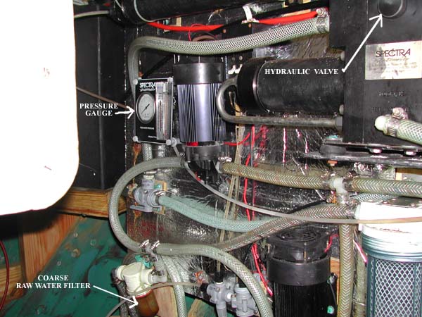
Overview: Water is pumped (at about 60 psi) into a hydraulic
mechanism that increases the pressure and is then pushed through a membrane.
Fresh water is produced on the low-pressure side of the membrane and remaining
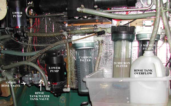
brine is pumped overboard. There are two 60 psi pumps, one higher then the
other. Using one will produce about 6 GPH @ 12 volts. Using two will produce
about 12 GPH @ 12 volts. We use one most of the time and save the second as a
backup. Also, the lower pressures of running only one seemed to cause fewer
problems.
There are three raw water intake filters, a coarse filter to
remove seaweed, a 20 micron paper filter and a 5 micron filter. The maintenance
of the 20 and 5 micron filters are key to proper operation. This is achieved by
the use of a 5-gallon storage tank (located under the quarter berth) that is
used to flush the system after use. What follows is a procedure that doesnt
match the one recommended in the owners manual, but it has proven to be the
best.
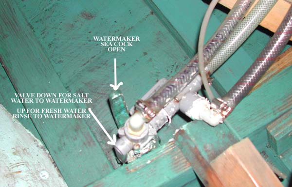
STARTUP: Check that the raw
water seacock is open (located port and aft in the engine room) and the gray
valve handle just above the seacock is pointing DOWN. This will allow raw water
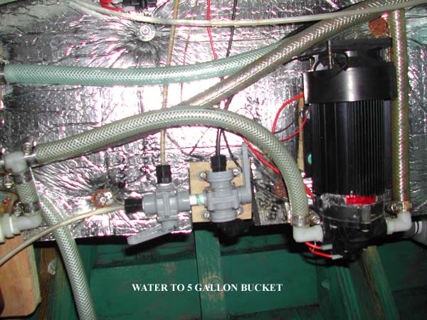
to the water-maker. The valve with the small hose attached should have its
handle facing AFT and the hose should be in the 5 gallon bucket. The valve just
forward of that valve should have its handle facing UP. This configuration puts
product water into the 5 gallon bucket. Turn on a pump switch (located just
forward of the upper pump). You can use either pump. Listen for the pump to slow,
or if the engine is running, watch for the pressure to rise on the monitor
gauge. This signals that the pump is primed. Gently tighten the round knob on
the hydraulic block clockwise. The pressure should increase to 60 lbs (about 9
oclock) and the hydraulic block should begin to cycle. You will hear or (if
the engine is running) feel a slight hammering every 10 seconds or so. The pressure
should gradually increase to 80 lbs (11 oclock). Water should be coming out of
the small hose and into the bucket in a pulsing but steady stream. Run about 1
gallon of water into the bucket (10 minutes on one pump).
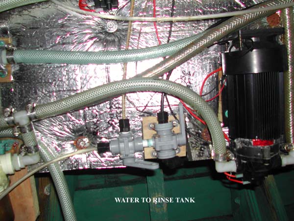
Move the valve lever at the small hose FORWARD. This will
put water into the 5
gallon rinse tank.
After about 45 minutes, check to see if water is filling up the milk jug that
is in front of the micron filters. This is the overflow for the rinse tank and
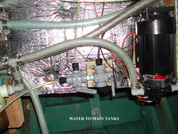
signals that it is full. Return the small hose valve to its AFT position and
test the water coming out of the small hose. Use the PPM gauge or just taste
it. If its OK move the lever FORWARD and the valve lever just ahead of it
DOWN. Fresh water will now begin to fill the 30 gallon plastic tank under the
galley sink.
The water tank deck fill valve (located at the aft end of
the starboard pilot berth) should be making a sad face. This allows water to
overflow from the 30-gallon plastic tank to the 50-gallon Nauta tank (located
under the port settee) once the 30-gallon tank is full.
SHUTDOWN: With the water maker still running, move the gray
valve above the raw water seacock to the UP position. This brings water from
the rinse tank to the water maker. Watch the pressure gauge to make sure it
stays above the 9 oclock position. If it falls, the pump has lost its prime.
Open the hydraulic block valve counter-clockwise ¾ of a turn and wait for the
pump to re-prime. When it does (pressure will increase slightly) GENTLY close
the hydraulic block valve. The watermaker should start cycling again. Watch the
hose on the forward side of the charcoal filter. Within a minute or so you
should begin to see bubbles in the line. Turn off the pump. Return the gray
valve just above the seacock to the down position. Put the small hose valve to
the AFT position and the valve immediately forward of that to the UP position.
Open the hydraulic valve ¾ of a turn. This will set the system up to be
re-started correctly. Remove both micron filters and rinse with the saltwater
sprayer at the galley sink. Remove as much debris from the pleats in the paper
filter as possible. Finish rinsing with the water from the 5-gallon bucket and
the milk jug. NEVER USE CLORINATED WATER TO RINSE FILTERS OR WATERMAKER. You
will ruin the membrane! Let the filters drip dry then replace.
You can avoid the shutdown procedure if you run the water maker
once a day.
Eventually, debris will accumulate in the micron filters and
warm tropical temperatures will sour the salt water remaining in the
watermaker. I recommend that water be made in large batches of 30-gallons or
more. Our procedure was to make water on approaching a port and leaving a port.
MISCELLANIOUS:
Porthole glass and hard dodger windows are all made of
Lexan. DO NOT CLEAN WITH ANYTHING BUT WATER, AS THEY WILL BECOME OPAQUE.